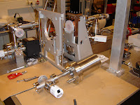
We have performed the first high power RF tests in May.
The RF setup is orginized in the following way:
- The output of the RF source, Phase-Locked Loop (PLL) Synchroniser, is fed to the 100-W continuous RF amplifier, MAL tld..
- Inside the PLL a RF switch is integrated at the output, so that we can produce a low power (13 dBm) RF pulse of tens of microsecond in duration.
- The MAL amplifier (type AM82-3S-45-50R) has a small signal gain of 41 dB and has a output maximum of 50.2 dBm.
- The output of the MAL amplifier is fed to the input of the Klystron Tube. The klystron tube has a small signal gain of 57 dB.
- At the output of the Klystron Tube the waveguide section (WR284) is mounted, which contains a circulator with load (Ferrite SC3-118), bi-directional coupler and RF pressure window (CPI VWX-1053) at the accelerator cavity.
- To the bi-directional coupler RF diode detectors (Agilent 423B) are connected to monitor the forward and reflected RF power.
In this test phase the RF pressure window is replaced by a reflection plate, so that all the RF power is dissipated in the RF load on the circulator.
In the control room we have placed all the measurement equipment: two puls generators to supply the trigger pulse for the modulator and RF switch inside the PLL Synchronizer. The signals are displayed on a oscilloscoop.
For the computer in the control room the modulator can be controlled and all the operating parameters can be monitored.

Upper: PLL Synchronizer, Lower: MAL RF Amplifier
| 
N-type Coax cable connected to RF input of Klystron Tube.
|

Bi-directional coupler in waveguide section. RF diode detectors connected to forward and backward outputs.
| 
Trigger signal generation and signal analyzing in control room.
|

Control computer in control room.
| 
Red warning light indicates accelerator operation.
|


