Wednesday, December 23, 2009

Latest news: new picosecond accelerator operational - 23th of December 2009

Our new picosecond pulsed high-energy electron accelerator has delivered its first pulses today (23 December 2009). Pulses are being produced for pump and probe experiments with a world-wide unprecedented high repetition frequency of 100 Hz.

This terrific achievement is the outcome of intense collaboration and commitment of technicians and scientists at the Department of Chemical Engineering and the Reactor Institute Delft.

In particular Martien Vermeulen and Walter Knulst have shown enormous persistence since they started the design and construction of the accelerator about four years ago.

The electron pulses will be combined with optical and terahertz probe pulses for studies on new materials for application in opto-electronics (e.g. solar cells) and nanomedicine.


Movie of the electron beam - 23rd of December 2009


1 - The Sample Chamber has an extra port through which we can see the sample in the Sample Chamber from the front side. This makes is possible to place a CCD Camera behind this window and monitor the beam position and shape by using a phorphor screen at the sample position.


2 - The CCD image. In the center you can see the phosphor screen positioned in the center of the Sample Chamber.


Here you can see the movie with the electron beam visible on the phospor screen.

UV generated electron pulse - 23rd of December 2009

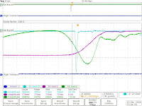
A view scope images. In purple the forward RF pulse, in green the reflected RF pulse, in light blue the beam dump signal measured over 50 Ohm.


1 - Clearly visible the large light blue spike which is the UV generated electron pulse measured in the beam dump.


2 - Same situation only now with the background of dark current visible. This can be achieved by changing the strength of the main magnet around the cavity.


3 - Now, we made the RF pulse shorter and changed the timing of the laser so that it arives at the end the RF pulse when the electric field in the cavity reaches it maximum.


4 - Zoom in at the end of RF pulse.

The Great Day - 23rd of December 2009

On the 23rd of December we prepared the UV laser beam and synchronization to excite the first electron pulses.


Walter Knulst and Martien Vermeulen who have contructed the picosecond-pulsed 4.5-MeV electron accelerator. This project could not have been successfull without the support and help of many people: John Suijkerbuijk, Paul Rijkers, Juleon Schins, Laurens Siebbeles, Rene den Oudsten, Raymon Bresser, Rene Gommers, Ruud van Tol, Eindhoven University of Technology, Pulsar Physics, and many others.


2 - On the scope screen in blue the UV excited electron pulse is visible. To celebrate this event a bottle of champagne is donated by Laurens Siebbeles, the initiator of the accelerator project.


3 - We invited a lot of contribitors to the construction of the electron accerlator to see the first electron pulses on screen and take part of the celibration.


4 - Taking a look at the setup.

5 - Taking a view at the setup.

Wednesday, December 2, 2009

Synchronization of laser system with accelerator - December 2009

In this post, I will present some details about the synchronization of the laser system with the RF electron accelerator.


1 - A photodiode monitors the 75-MHz output of the Ti:S oscillator. This signal is transported to a Phase Lock Loop than synchronizes a 3-GHz Voltage Controlled Oscillator to this laser, with ability to control the phase. This system has been published by Kiewiet et al. in 2001. The laser oscillator is the main clock of the system. To match the derived 3-GHz frequency to the resonance frequency of the RF cavity, the laser cavity length can be changed by displacing one of the end mirrors.


2 - These two boxes allow us to trigger the laser system by one external trigger from the main Trigger and Delay Generator. One trigger to the laser system leads to a pulse from the high power pump laser of the amplifier and the pulse selection by the two Pockel Cells in the regenerative amplifier cavity. This system operates at 1-kHz frequency.


3 - Because the accelerator operates at 100-Hz or lower frequency the laser frequency is down shifted by the use of a chopper and shutter combination. The chopper decreases the frequency to 100-Hz from which a fast shutter can select only a single pulse or it sub harmonic. We perform this operation to prevent the cathode of the RF cavity of being exposed to too many laser pulses that can cause damage.


6 - In front you can see the shutter and in the back the vacuum laser transport line to the accelerator room.


7 - The chopper and shutter controllers. The chopper is synchronized to the 1-kHz trigger of the laser system. Then only the right phase has to be selected to pass the right laser pulse from the 1-kHz train.

Details of Laser Beam - December 2009

In this post, I will present some details of the optical layout.


1 - This is the side optical table. In the right corner in the front the laser beam transport line can be seen. Through this vacuum line the 800-nm fundamental laser beam from the Ti:S amplifier is transported. Using vacuum reduces instabilities in the laser beam caused by turbulence of air flow.


2 - We choose to transport the stretched amplified laser pulse directly output of the regenerative amplifier. At the output of the laser system a telescope is positioned to shape the laser beam to a smaller size. On this picture you see the compressor that is positioned on the side table.


3 - After the compressor the laser beam passes through the second and third harmonic unit. The third harmonic is used either to generate the electron pulse at the cathode surface of the RF cavity or excite the sample optically. The left over fundamental beam will be used to probe the sample. If necessary this fundamental wavelength can be converted into other wavelengths by using for instance white light generation.


4 - Around the Sample Chamber a frame is mounted to hold the opto-mechanical components. The laser beams (pump and probe) have to be deflected upwards to reach the windows of the vacuum system.


5 - Detail of the UV in coupling. One can see the prism's in the cross.


6 - Detail of the probe laser beam transport line to the window of the Sample Chamber.

Tuesday, December 1, 2009

Details of Sample Chamber - December 2009

In this post, I will introduce some details of the Sample Chamber and explain their function.


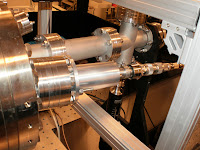
1 - At the side of the Sample Chamber one can view through a big window into the chamber and see the carousel holding multiple samples. We have a standard piece mounted with diaphragm’s, a phosphor screen and test samples such as ZnS and ZnSe.


2 - The rotational feed through mounted on a x,y,z stage. We can rotate the right sample into the electron beam, retract the complete carousel out of the electron beam line and displace the sample through the electron beam.


3 - Behind the sample chamber but before the electron beam dump a beam viewer can be inserted into the electron beam. Using a Gigabit Ethernet CCD Camera we are able to follow the electron beam at a high frame rate.


4 - Here you see the beam dump at the deflected output port of the sample chamber. Using this beam dump, we can optimize the electron beam without irradiating the sample and causing unwanted degradation.


5 - Input window of the laser beam to the sample. We are not only able to excite the samples with the electron pulses, but in the same sample chamber we can excite them also with the laser pulse. In this way we can compare laser flash photolysis with electron beam photolysis without exchanging the sample to different experimental setups.