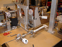
This week we have installed the magnet around the cavity. This magnet will collimate and focus the electron beam exiting the accelerator cavity.
The magnet consists of an iron return joke and of hollow copper windings for water cooling. The windings are separated into nine sections. The current is connected in series through the section, while the water cooling is parallel through the section.
Friday, June 22, 2007
Cross Section of Accelerator Cavity
 This pictures shows a cross section of the electron accelerator that will be installed.
The cavity consists of two cells: one 0.6 cell and one full cell. The design frequency is 2998.5 MHz (about 10 cm wavelength in vacuum). The RF waves are coupled in axial by the coaxial line. The RF waves are converted from rectangular to coaxial waveguide by the RF input coupler. The inner counductor is hollow to pass the UV excitation pulse and electron bunch.
An ultrashort UV pulse illuminates the cathode surface. By the photolectrical effect electrons are emitted from the copper cathode (up to 1 nC). These electrons will experience the very high acceleration field (about 100 MV/m) inside the cavity. Due to the very high field strength the bunch leving the cavity will be still very short, about 1 ps. The final electron energy is little less than 5 MeV. The required RF power is roughly 8.5 MW peak power during a few microseconds.
Special feature of this cavity (designed by the Eindhoven University of Technology) is the fact that the cells are no longer brassed together but pressed by screws. Therefore, a stainless steel container is needed for vacuum purpose. However, due to the fact that the faces of the copper parts are turned by single diamand turning machines a very large compression rate is expected between the inner and outer vacuum sections.
On the outside of the copper cavity cooling and heating facilities are designed. There are in total three seperate cooling channels: 1- integrated in the cathode part, 2- integrated in the center iris part, 3- on the RF input coupler. There are two integrated heating elements (Thermocoax): 1- on the cathode part, 2- on the iris part. Two thermocouples will measure as good as possible the local temperature of the cells. Through the back flange of the stainless steel container several feedthrough can be seen to support all those features.
The back flange of the stainless steel container contains also a bucking coil. This magnet compensates locally on the cathode surface the magnetic field generated by a big magnet around the cavity. For electron beam optical reasons the magnetic field has to be zero at the point where the electrons are generated.
Due to the cilindrical symmetrical design a magnet can be placed around the cavity to focus the electron beam exitting the cavity.
Test installation of vacuumsystem - 4th of June 2007
We have made the first test assembly of the vacuumsystem of the electron accelerator.
The cavity consists of two vacuum sections:
The cavity consists of two vacuum sections:
- inner part, which are the cells of the cavity that will be pumped to a pressure below 10-9 mbar by a Varian iongetter pump of type VacIon 150.
- outer part, which is the space between the copper cavity and the stainless steel container that will be poump to a pressure of about 10-6 mbar by a Varian iongetter pomp of type VacIon 20.
Tuesday, June 19, 2007
Electron Bunch Length Measurement
Electro-optic technique for real-time, non-destructive, single-shot measurements of femtosecond electron bunch profiles.
Explanation of measurement technique can be found at the website of Geil Berden at the FOM-institute for Plasma Physics Rijnhuizen in The Netherlands.
Explanation of measurement technique can be found at the website of Geil Berden at the FOM-institute for Plasma Physics Rijnhuizen in The Netherlands.
 |  |
 |
Announcement conference PULS'2008

The 8th International Conference on Pulse Investigations in Chemistry, Biology and Physics PULS'2008 will be held on September 6 - 12, 2008, at Guest House of the Jagiellonian University "PRZEGORZAŁY" in Kraków, Poland.
Chairmen: Krzysztof Bobrowski (INCT) and Jerzy Lech Gębicki (IARC).
Chairmen: Krzysztof Bobrowski (INCT) and Jerzy Lech Gębicki (IARC).
Wednesday, June 6, 2007
Poster NWO Spectroscopie en Theorie Meeting 2007
Poster presented at the NWO Spectroscopie en Theorie Meeting 2007:
Abstract and Presentation Miller Conference 2007
You can find my abstract and presentation of the Miller Conference 2007:
Subscribe to:
Comments (Atom)


