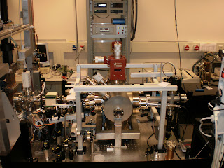
 1- Directly behind the RF cavity and RF input coupler a valve is positioned to separate the vacuum compartment of the cavity from the rest of the setup.
2- Then around the bellows a steering magnet is positioned. With this magnet we are able to position the electron beam on the sample and find the overlap with the probe beam. The probe beam is a time delayed ultrashort laser pulse than analyses the status of the sample after being excited by the electron pulse.
Additionally, we are able to displace the electron beam over the full sample surface. This is necessary, because the electron pulse is causing irreversible damage to the sample. By taking each time a fresh piece of sample, the measurement time can be extended before replacing the sample.
 3 - Next, we have a cross-piece which is used to couple the UV pulse into the vacuum system to illuminate the cathode surface and generate the electron pulse. We use 266-nm laser light, which is the third harmonic of the 800-nm fundamental wavelength coming from a Ti:S amplifier.
 In this cross-piece two aluminum coated prim's are mounted on a moving base. This base is constructed in such a way that when rotating the feed through below the gap between the prima's can be varied. One has to realize that the UV beam has to pass through the inner conductor in the coaxline upstream to the cavity. This has a narrow diameter. On the other hand, the prism's have to be placed to the side, because the electron beam is passing through the center. Due to the control of the gap, we can find the optimum position of the prisma's. Finally, the reflection of the UV pulse on the cathode surface can be seen at the output window. This is essential to find with the UV laser beam the center of the cathode surface. One can see all the diamond turning rings in the reflection of the UV laser beam.
4 - Sample chamber. It is a very complex piece. The essential function is that a carousel with multiple samples can be positioned with respect to the electron beam using a rotational feed through with x,y,z linear stages. The chamber has four laser windows (two input and two output) mounted at small angles with respect to the electron beam to probe the sample. We like to setup a visible probe line and a infrared probe line.
 5 -In front of the sample chamber a bending magnet is mounted. This enables us to deflect the beam away from the sample into a side beam dump. This function serves multiple purposes: We can scan the electron beam energy; We can optimize the phase injection of the UV laser beam into the RF cavity; We can measure the background level to correct the measurement; By rapid switching of this magnet we prevent the sample from degrading and exposure to excessive electron pulses.


